Formhauptsignal (DB)
Signal-ID: 210 (hex: 0xD2)
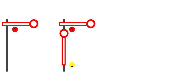
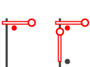
Using this signal configuration, the following signals can for example be operated:
- Single arm (Hp0)
- Single arm (Hp1)
- Double arm (Hp0)
- Double arm (Hp1)
- Double arm (Hp2)
Semaphore signals can be connected if they fulfil the following conditions:
- Drives switched off at end of travel
- Current consumption < 400 mA per drive
- Common anode
- One control line per signal aspect
Attention: The semaphore signals produced by Viessmann and also sold by Roco/Fleischmann with two drive cylinders require positive control pulses (= common cathode)! To be able to connect these signals directly, one would require a control module with a common anode, which however is no longer available from the manufacturer.
If you have experience in soldering and electronics, then there would be a DIY
solution: If you were to carefully cut open the sheath on the electronic ballast of
the signal, you would see four diodes in one direction. It would then be necessary
to unsolder these four diodes and to solder them back in again after rotating them
180 degrees. However, we hereby note that we cannot expressly recommend this
procedure, as then the warranty on the signal would expire.
This conversion would only be required on the above-mentioned signals with
two drive cylinders. The other semaphore signals with only one
drive cylinder can be connected directly to the decoder.
Terminal assignment
1 - Red+Green+Yellow LED
Lighting
2 - Coil
Connection for “Hp0”
3 - Coil
Connection for “Hp1”
4 - Coil
Connection for “Hp2”
5 - Coil
Identical with terminal 2 for more power
6 - Coil
Identical with terminal 3 for more power
7 - Coil
Identical with terminal 4 for more power
8 - Reserved
Decoupled double arm semaphore signals may consume more current when switching between "Hp0" and "Hp2" because both arms have to be moved at the same time.
To avoid short-circuits, the connections for the magnetic drives are doubled. If applicable, connect the signal line for "Hp0" with the terminals 2 and 5, those for "Hp1" with the terminals 3 and 6 and the signal line for "Hp2" with the terminals 4 and 7.
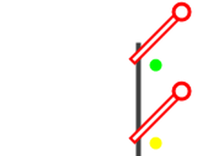
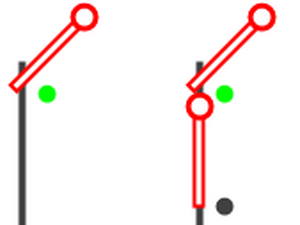
Signal aspects
Hp0
DCCext
0
Trigger
1R
Stop
Hp2
DCCext
4
Trigger
2G
Proceed slowly
Hp1
DCCext
16
Trigger
1G
Proceed