Legend
The description of the signal configurations is structured as follows:
- Signal ID
- Brief description and intended purpose
- Assignment of terminals
- All available signal aspects
- If applicable all available signal aspects sorted according to mode
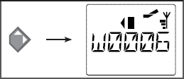
1. Signal-ID: 242 (hex: 0xF2)
The Signal-ID explicitely defines the signal configuration and the type of
signal described. The specification is made in decimal as well as in hexadecimal
format ("0xF2") for the advanced user.
The Signal-ID is also the value that can be written in CV41 to CV44 of the Z21
signal DECODER in order to configure the first to the fourth signal to the desired
type of signal.
2. Brief description and intended purpose
The following provides a brief description and a list of signals that can be operated with this signal configuration. This list does not lay any claim to completeness. For reasons of space alone it sometimes is impossible to always list all conceivable equipment variants and lamp arrangements of the prototype. Instead we try to show the most important and common examples of the signal type.
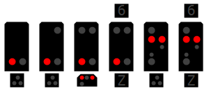
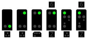
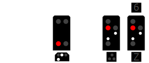
3. Terminal assignment
The assignment consists of a graphic with the most common assembly variants of the
signal configuration as well as a table.
In the graphic there is a small number at each lamp which describes the
terminal of the Z21 signal DECODER the lamp should be connected to.
The table contains again the color of the lamp and if necessary a short
description for each terminal used for an easier assignment.
Example:

Terminal assignment
1 - Red LED
Brief descprition of the lamp, relevant signal aspects, ...
2 - Violet LED
3 - Green/White LED
Sometimes different lamp colors can be connected depending on the type of signal
4 - Yellow LED
(Optional) - Sometimes not all terminals are required depending on the assembly variants of the signal and therefore they are optional
4. Signal aspects
The table of signal aspects on the very left is always labelled with a name or a short description of the signals.
In the table then there are listed the values for the DCC Extended Accessory Command switching command and the DCC Basic Accessory Command.
The Z21 signal DECODER can either be operated with DCC Extended Accessory Commands or with the DCC Basic Accessory Commands.
Name/Brief description
DCCext
= Value for DCC Extended Accessory Command
Trigger
= Switching command for switching the lamps for DCC Basic Accessory Command
Mode
= Switching command for DCC Basic Accessory Command
DCC Extended Accessory Command
= Value which can be used for switching the signal aspect via switching commands in
the DCCext - DCC Extended Accessory Command
format.
Attention: Not every DCC control centre is capable of
this relatively new extended accessory command format. If necessary, check whether
there is a corresponding firmware update available for your control centre. In the
Z21 product family the DCC extended accessory command format is implemented from
firmware V1.40 onwards, an update for the Z21 app will
follow.
The extended accessory command format allows a number between 0 and 255 to be
transmitted to the Z21 signal DECODER which precisely defines the desired signal
aspect.
The valid values depend on the specific signal, but common values are for
example:
- 0 ... absolute stop aspect.
- 4 ... Proceed with speed limit 40 km/h
- 6 ... Proceed with speed limit 60 km/h
- 16 ... Clear
- 65 (0x41) ... Shunting allowed
- 66 (0x42) ... Dark switching (e. g. light distant signals)
- 69 (0x45) ... Substitution signal (permits trains to pass)
For these examples too, the value will only be accepted by the Z21 signal DECODER if the desired signal aspect is acutally available and appropriate for the selected signal type.
On the other hand, the following also applies: The value of a desired signal aspect will be accepted by the Z21 signal DECODER even if the desired aspect is generally available on the selected signal type but can not be correctly displayed by the actually connected signal due to a not assembled lamp. This is not an error in the Z21 signal DECODER. The Z21 signal DECODER can not detect missing lamps automatically and it must always assume a fully equipped variant of the signal type. Therefore the user is responsible for only using appropriate and actually presentable signal aspects.
Example: You want to display "Hp2" (Proceed with speed limit 40 km/h) on the DB H/V Hauptsignal with Green+Yellow but the yellow lamp is missing on the connected signal. Nevertheless the command will be accepted by the Z21 signal DECODER because the selected DB H/V signal system generally knows this term and the Z21 signal DECODER can not know at all that the yellow lamp is missing on the connected signal. In this example"Hp2" can not be displayed correctly - so do not switch "Hp2" if your signal is not capable of displaying this signal.
DCC Basic Accessory Command
= Value with which the signal aspect can be switched with normal switching commands for turnouts as they have always been available on a multiMAUS or a legacy command station. Those switching commands are the widespread DCC Basic Accessory Commands.
- The column "Trigger" describes the switching command that leads to the switching of the lamp.
- The colum "Mode" describes the switching command with which a
specific group of up to four signal aspects can be preselected beforehand.
"Mode" is usually only necessary if a signal type knows more than 8 different signal aspects, otherwise there is no value for "Mode".
The notation for trigger and mode works according to the following scheme: Number (1 to 4) + Letter ("G" or "R"): 1R, 2R, 3R, 4R und 1G, 2G, 3G, 4G.
- The number leads to the "turnout number" which is entered into the multiMAUS
and which the switching command is transmitted to. This number results of the
signal address:
You have configured your signal to signal address 1?
Then send the command R to turnout number 1, 2R to turnout number 2, 3G to turnout number 3 and 4R to turnout number 4.
You have configured your signal to signal address 5?
Then send the command 1R to turnout number 5, 2R to turnout number 6, 3G to turnout number 7 and 4R to turnout number 8.
(etc.)
Quick reminder: each signal always occupies four "turnout numbers" if the Basic Accessory Command format is used. Valid signal addresses are therefore 1, 5, 9, 13, ... - The letter describes the command more precisely:: G="Green"="straight turnout position" and R="Red"="branching turnout position".
Example: You have configured your signal to signal address 1 and want to send the switching command 1G with the WLANMAUS
Example: You have configured your signal to signal address 5 and want to send the switching command 1R with the WLANMAUS
Example: You have configured your signal to signal address 5 and want to send the switching command 2R with the WLANMAUS
For signals with more than 8 signal aspects the commands 1G, 1R, 2G, 2R are usually
used for Trigger and the commands 3G, 3R, 4G, 4R for Mode.
This results in up to 4 * 4 = 16 combinations which up to 16 different signal
aspects can be switched with.
For signals with only 8 signal aspects max., those can be switched directly via the Triggers 1G, 1R, 2G, 2R, 3G, 3R, 4G or 4R.
The rules explained above also apply for the Basic Accessory Command format: The Z21 signal DECODER only accepts signal aspects that are practical and available for the selected signal type but it can not detect missing lamps automatically and if therefore a specific signal aspect can not be displayed correctly. Therefore the user is responsible for only using appropriate and actually presentable signal aspects.
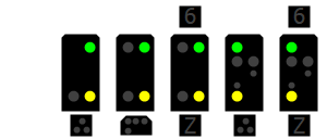
5. Sorted according to mode
For signals where the column "Mode" is not empty (i. e. more than 8 signal aspects) the table with available signal aspects is repeated once again.
However, the table is sorted according to groups that result from a common value for "Mode".
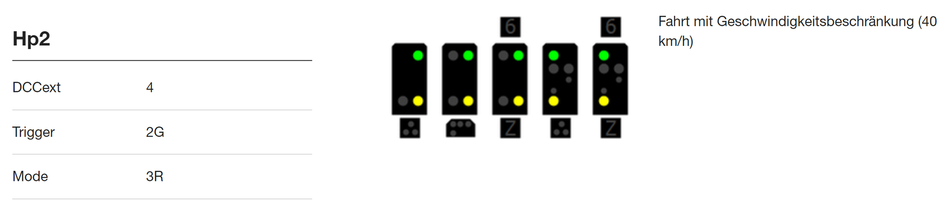
Example DB H/V Hauptsignal, Mode = 3R. This is the group with the most important signal aspects Hp0, Hp1, Hp2 and Sh1:
Hp00 / Hp0+Sh0
Trigger
1R
Mode
3R
Hp1
Trigger
1G
Mode
3R
Hp0+Sh1
Trigger
2R
Mode
3R
Hp2
Trigger
2G
Mode
3R